01
Consultation
Technical needs assessment

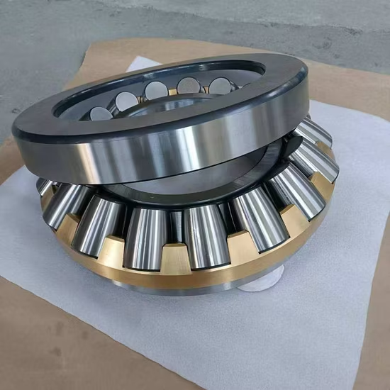
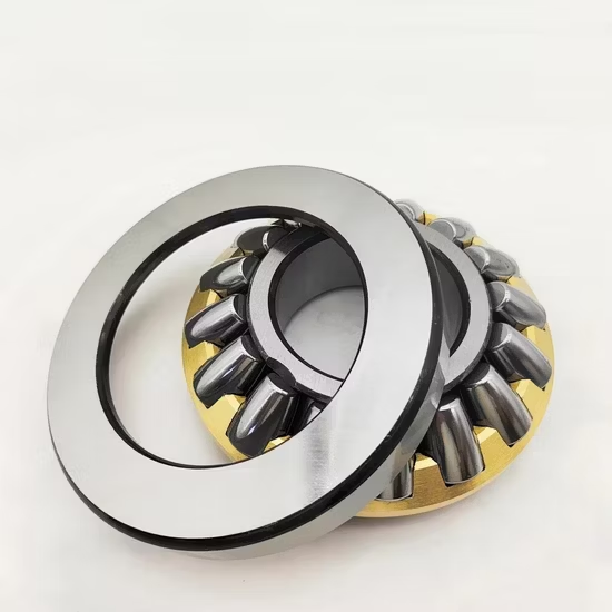
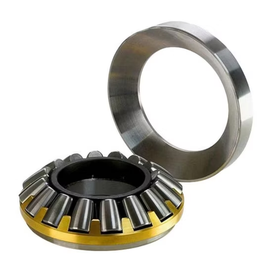
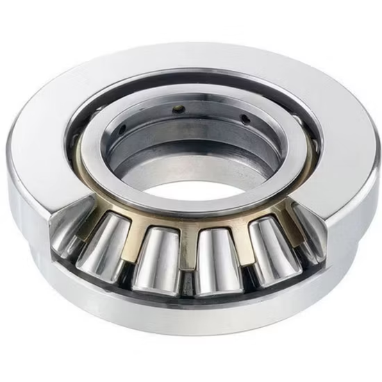
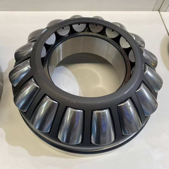
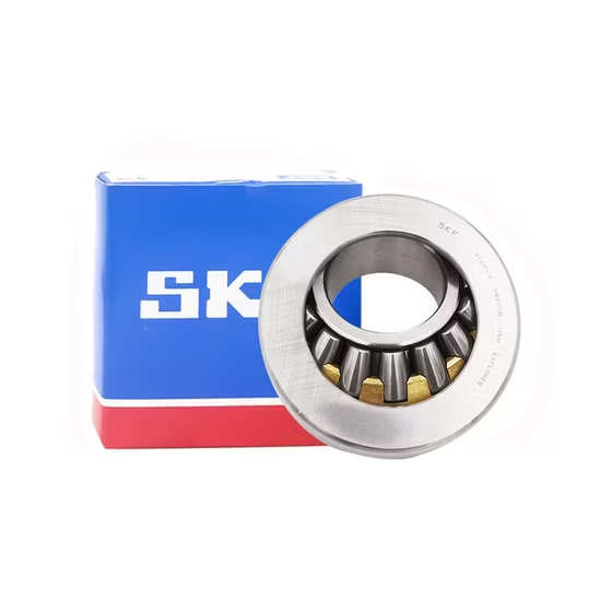
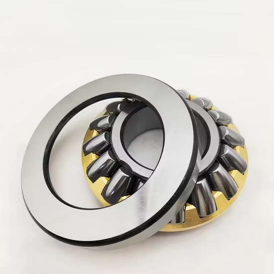
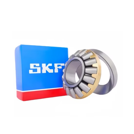
29416m Spherical Thrust Roller Bearing 80×170×54 mm — The machined brass cage (m suffix) provides high strength and heat dissipation under heavy axial loads, while the spherical raceway accommodates static misalignment.
Authenticity via official apps — Every 29416m spherical thrust roller bearing ships with verifiable QR codes readable through manufacturer applications to confirm batch origin.
| Parameter | Value |
|---|---|
| Designation | 29416m |
| Bearing Type | Spherical Thrust Roller Bearing |
| Bore Diameter (d) | 80 mm |
| Outside Diameter (D) | 170 mm |
| Width (T) | 54 mm |
| Cage Material | Machined brass (m suffix) |
| Origin | Germany / Japan / Sweden / Malaysia / China |
| HS Code | 8482500090 |
| Industry | Typical Applications |
|---|---|
| Mining and crushing | Gyratory crusher main shaft thrust support |
| Heavy-duty gearboxes | Extruder screw thrust absorption |
| Material handling | Bucket elevator drive shaft axial positioning |
| Marine drives | Propeller shaft thrust collars |
Thrust roller bearings inherently lack the speed capacity of radial designs, making thermal management the primary survival factor.
I once watched a client install this exact designation in a high-RPM setup, assuming the heavy-duty build meant it could handle the velocity. The low limiting speed of spherical thrust rollers caused rapid heat buildup, melting the cage and seizing the shaft. Cross-referencing errors that ignore the fundamental speed limits of thrust designs lead to catastrophic field failures, not just minor inefficiencies .
The 29416m spherical thrust roller bearing handles extreme unidirectional axial loads while accommodating static misalignment between the shaft and housing. This specific capability prevents edge-loading on the rollers when heavy machinery frames deflect under operational stress. Our technical review process ensures the axial capacity aligns with your actual equipment thrust before confirming the order.
Heavy axial loads generate substantial friction heat within the roller-raceway contact zones. Oil lubrication is typically mandatory to carry this heat away, as grease cannot dissipate thermal energy fast enough in continuous heavy-duty cycles. Contaminant exclusion remains critical in mining environments, requiring effective sealing arrangements on the housing rather than relying on the bearing itself .
The lowercase m suffix designates a machined brass cage, which provides superior structural integrity under heavy axial loads compared to pressed steel alternatives. Brass offers excellent heat dissipation properties and maintains dimensional stability when subjected to the high contact stresses typical in extruder or crusher applications. This cage design also ensures reliable roller guidance during the low-speed, high-load operational cycles characteristic of thrust applications.
Procuring a base number match while overlooking the cage material suffix frequently results in pressed steel cages being installed where machined brass is required. Under heavy axial shock loads, a weaker cage will deform, causing roller skewing and rapid raceway spalling. Such premature failures trigger unplanned downtime and void equipment warranties, as the failure mode clearly indicates incorrect component specification per ISO 15243 classification .
We secure the exact 29416m spherical thrust roller bearing with the correct machined brass cage, avoiding the common trap of suppliers substituting unavailable variants without technical approval. Our cross-brand interchange expertise matches the internal design and cage material, not just the basic dimensions, ensuring drop-in replacement without thermal binding. Furthermore, we provide application-based selection reviews to verify that your operating speeds remain safely within the limiting thresholds of this thrust design.
To ensure the 29416m spherical thrust roller bearing meets your operational demands, please provide your specific axial load profiles, operating speeds, and thermal conditions. Sharing the OEM equipment number allows our engineering team to perform a precise cross-reference check, verifying that the cage material and internal geometry match the original design intent. This technical validation prevents the costly installation of under-specified thrust components in critical heavy-duty machinery.
Q: How can I verify the authenticity of the received bearings?
A: Authenticity is confirmed by scanning the QR code on the packaging using the manufacturer's official mobile application. This digital verification links the specific batch and lot number directly to the factory's production records, ensuring the machined brass cage and internal geometry meet original specifications and protecting your operation from counterfeit components with soft inner rings.
Q: Why is matching the cage suffix critical during cross-referencing?
A: The lowercase m suffix dictates a machined brass cage, which is essential for dissipating heat and maintaining roller alignment under heavy axial loads. Substituting a base number match that features a pressed steel cage will lead to rapid deformation and catastrophic failure in high-stress applications like crushers or extruders, making exact suffix alignment mandatory for operational reliability.
Q: What are the best practices for mounting spherical thrust roller bearings?
A: Proper mounting requires ensuring the housing seat is perfectly clean and aligned to utilize the spherical raceway's self-aligning feature. The shaft ring should be induction-heated to the recommended temperature for a secure interference fit, while the housing ring must be installed with the correct clearance to allow for thermal expansion and prevent axial binding during heavy load cycles.
Q: How should lubrication be managed for heavy axial load applications?
A: Continuous heavy axial loads generate significant friction heat that grease cannot adequately dissipate. An oil bath or forced oil circulation system is typically required to cool the roller-raceway contact zones and flush out wear debris. Relubrication intervals must be calculated based on the specific operating temperature and load magnitude to maintain a protective hydrodynamic film.
Our 5-step process ensures every order is engineered, validated, and supported for optimal performance.
Technical needs assessment
Custom specifications
Free samples for $50k+
Pre-shipment inspection
On-site & predictive
Our certified engineers respond within 24 hours with detailed technical specifications, pricing, and lead time information.